
AAPL
Advanced Aero Propulsion Laboratory
AAPL
Advanced Aero Propulsion Laboratory
Imagination is more important than knowledge. For knowledge is limited to all we now know and understand, while imagination embraces the entire world, and all there ever will be to know and understand.
—Albert EinsteinUnsteady actuators with high amplitude response and tunable frequency are essential for the effective control of many subsonic and supersonic flows. Our current research focuses on the development, design, characterization, and modeling of various high-bandwidth micro-fluidic actuators and its implementation to various flow control applications. These projects are currently funded by AFOSR and FCAAP.
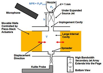
The actuator configuration capable of producing high band-width supersonic pulsed microjets (Resonance Enhanced Microjets, REM) is shown below. The first generation actuator (REM GEN1) system consists of a primary source jet under expanded into a generic short cylindrical cavity and an array of microjets emanates out of the cavity though multiple micro orifices integrated at the bottom side of the cavity. These pulsed microjet arrays can be tuned to any desired frequency in a range of 1-60 kHz by suitable variation of the geometric and/or flow parameters of the REM actuator. Characterization of the REM GEN1 actuator indicates a strong correlation between the actuator frequency and its geometry as shown in figure (b). More details are available in Solomon et al. (AIAA J, 2010).
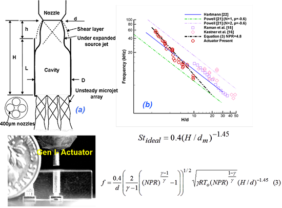 Figure 1: Experimental studies on REM actuator GEN I.
The REM GEN II design is shown in Figure (c). The pulsing microjets can be distributed in a linear or circular array pattern so that such configurations can be implemented in various practical applications that require high frequency excitation. Figure (d) shows the pressure fluctuation measured inside the actuator cavity of a REM actuator using a Kulite pressure sensor flush mounted on the actuator cavity side wall. A large unsteady pressure oscillation inside the actuator is clearly evident from this study.
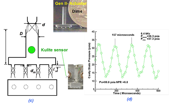 Figure 2: Experimental studies on REM actuator GEN II.
The flowfield of the REM actuator is captured using highly sensitive, high-magnification micro-schlieren system that uses laser induced plasma as a light source. The pulse width of this light source is very small (of the order of nano-seconds) so that it can freeze the flow features of such high frequency microscale resonant flows. The figure given below shows a phase locked schlieren images of the REM actuator flowfield at various phases of flow oscillations. More details this study is available in Foster et al. (AIAA paper 2011).
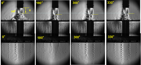 Figure 3: Flowfield of REM actuator showing periodic oscillation of Mach disc of the source jet.
A comprehensive numerical study on the REM actuator was carried out to better understand the resonant mechanism and its properties. The following figure compares instantaneous flow features of the REM actuator captured using a phase locked schlieren technique to the computer simulations. A very good agreement is seen between experimental data and the simulation results. More details of this study are available in Uzun et al.(AIAA paper 2011-2938).
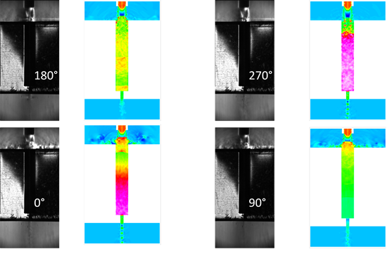 Figure 4: Comparison of phased locked schlieren images of the REM actuator flowfield and simulated results.
The third generation resonance-enhanced microjet (REM) actuator has been developed with smart materials incorporated into the design (Smart REM). The smart materials are used to precisely control some of the geometric properties of the actuator. Currently, a set of piezo-electric stack actuators are used to vary the micro-actuator’s volume by displacing a set of movable walls within the micro-actuator (see Fig. 5). The piezo-electric stack actuators consist of a set of cylindrical lead zirconate titanate (PZT) ceramic disks stacked on top of one another (see Fig. 6). This type of piezoceramic material is capable of producing very accurate displacements at high frequencies when a prescribed voltage is applied across each disk. By controlling the input voltage to the piezo-stacks, one can actively vary the micro-actuator’s volume thus changing its resonance characteristics and the pulsing frequency of the microjets. The fast response times and accurate displacements of the piezo-stacks are being utilized to obtain extremely precise control over the micro-actuator’s response frequency on small enough time scales such that we may also achieve accurate phase control for the REM actuators.
Figure 5: Resonance-Enhanced Microjet (REM) actuator with active structures (SmartREM). |
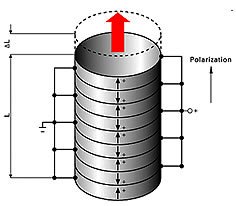
Figure 6: Cylindrical piezo-electric stack actuator schematic. |
|
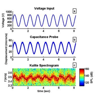
A number of piezo-stack control signals have been used to characterize how the micro-actuator responds to volume changes. An example control signal consisting of a full-scale, 1 Hz sine wave is shown in Fig. 7a below. The resulting piezo-stack displacement and micro-actuator frequency response are shown below in Figs. 7b&c, respectively. To see how the micro-actuator’s frequency evolves in time, the spectrogram of an unsteady pressure signal is shown. The spectrogram clearly shows that the micro-actuator’s frequency evolves in a sinusoidal manner in time, agreeing well with the control signal and displacement. A number of various control signal inputs have been studied, including higher frequency sinusoidal signals on the order of a few hundred Hertz, stair-step type signals, and short-duration pulse trains. Current experimental studies aimed at developing phase control for the REM actuators are showing promising results that indicate that the Smart REM actuator will be a successful active, feedback flow control actuator for a number of sub- and supersonic flowfields. More details can be found in Kreth et. al. (AIAA-2011-2939). |
Figure 7: SmartREM actuator with 1 Hz sine wave input. a) voltage input; b) piezo-stack displacement; c) micro-actuator frequency response varying in time. |
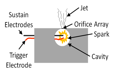
The sparkjet actuator is a zero net mass flux flow control device. The heat from an electrical discharge in air is used to create a temporary jet. The actuator used is composed of the following components: sustain electrodes, trigger electrode, cavity, and orifice array (Figure 1). The cavity is formed from a square piece of Macor with a hole drilled defining the outer diameter of the cavity and two glass disks forming the sides of the cavity. A second hole was drilled in the Macor to secure a circular Macor piece used as the electrode holder. Two of the electrodes (Sustain Electrodes) are connected to a capacitor bank sustaining 600 V. A short duration high voltage (1-12kV) pulse on the third electrode is used to ionize the space between the Sustain Electrodes, thus causing an arc discharge of the capacitor bank on the sustain electrodes. A photograph of this setup is shown in Figure 1b. The spark generated by this discharge transfers heat to the gas inside the cavity generating the pressure to create and sustain zero net mass flux jets, which exhaust through the orifice array. The orifice array is made up of four holes that are 400 µm in diameter.
 align="center"> Figure 8a: SparkJet Array Diagram
|
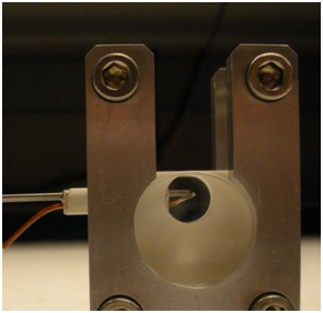 Figure 8b: SparkJet Array
|
Images have been taken of the actuator using a laser-based micro-schlieren system, and are show below. Also, the Shock and jet front speed can be calculated through the displacement of the two in consecutive images with a known time between. This can also be seen below.
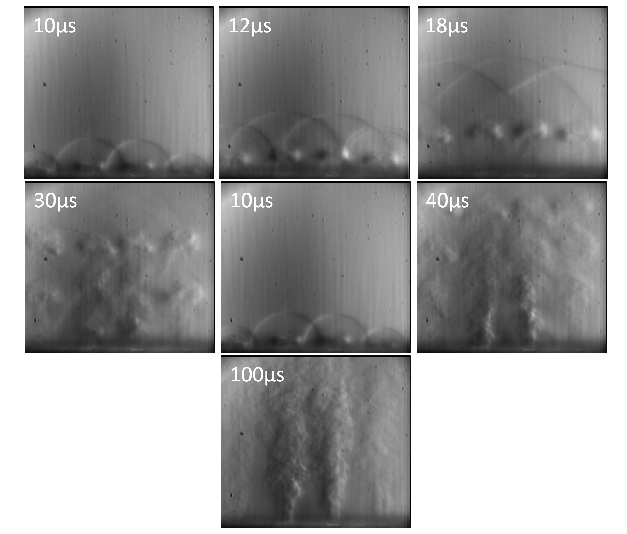 Figure 9: Trigger Train
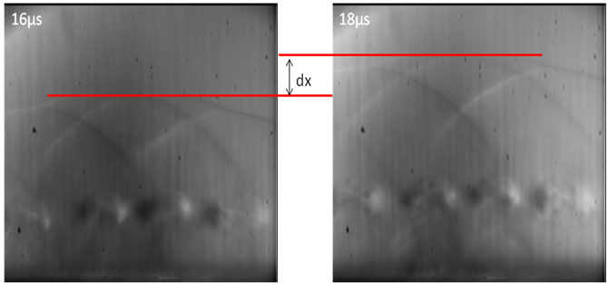 Figure 10: Shock Progression Between 16 and 18 µs