

AAPL
Advanced Aero Propulsion Laboratory
AAPL
Advanced Aero Propulsion Laboratory
Imagination is more important than knowledge. For knowledge is limited to all we now know and understand, while imagination embraces the entire world, and all there ever will be to know and understand.
—Albert Einstein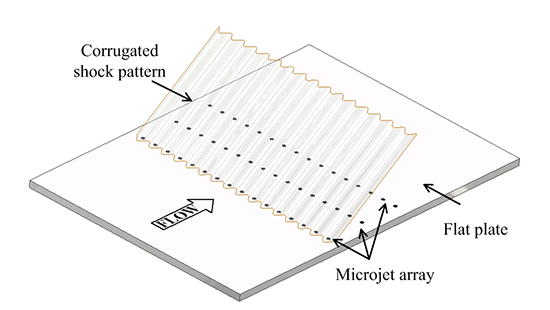 |
| Figure 1: Schematic of corrugated shock pattern with microjet array. |
 |
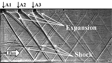 |
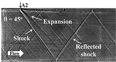
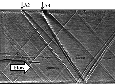
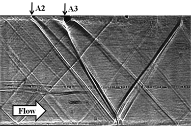
| Figure 2: Shadowgraph image(Left) single microjet generated shock, expansion following the shock and the reflected shock wave (Right) Parallel shocks using three microjet arrays. |
 |
 |
 |
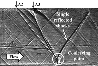 |
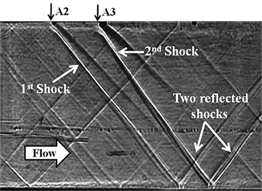
| Figure 3: Coalescing shocks generated using two microjet arrays. |
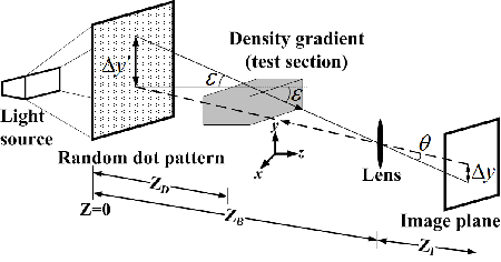
The principle of the technique is the refractive index variation due to density gradients in the flow. The determination of the density field using BOS involves the following steps: a) calculation of displacements in the background which is imaged through the flow of interest. b) calculation of the line-of-sight integrated density field by solution of the Poisson equation, which is the gradient of the above displacement; c) use of optical tomography (filtered back-projection) to determine the density field in the actual plane of interest.
 |
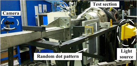 |
| Figure 4: (Left) Optical path for density gradient measurements by light deflection, (Right) BOS setup in a supersonic wind tunnel. |
 |
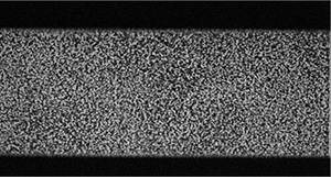 |
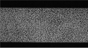
| (a) Raw Image - No flow (reference). | (b) Raw Image – Flow with microjets. |
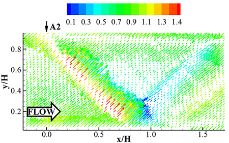 |
| (c) Vector of density gradients for single array (A2) operating at MPR = 1.9. |
| Figure 5: Instantaneous BOS images and density gradients obtained from cross-correlation of raw images. |
 |
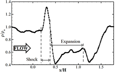 |
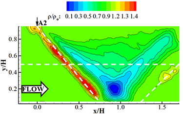
| (a) Average density field. | (b) Extracted density profile along centerline. |
| Figure 6: Single oblique shock generated by microjet array A2 operating at MPR = 1.9. |
 |
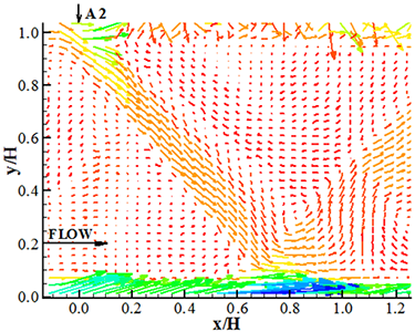 |
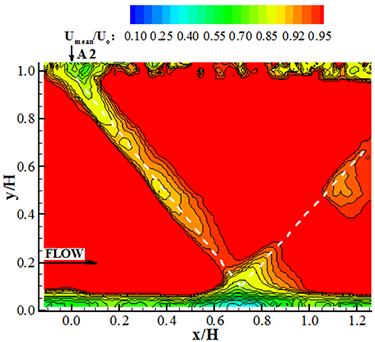
| (a) Contours of mean streamwise velocity. | (b) Averaged vector field. |
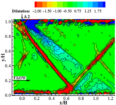 |
| (c) Dilatation. |
| Figure 7: Velocity field of microjet generated shock at MPR = 3.6. |