

AAPL
Advanced Aero Propulsion Laboratory
AAPL
Advanced Aero Propulsion Laboratory
Imagination is more important than knowledge. For knowledge is limited to all we now know and understand, while imagination embraces the entire world, and all there ever will be to know and understand.
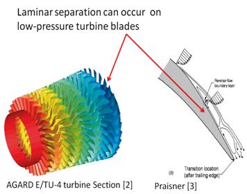
—Albert EinsteinAt high altitude cruise conditions the Reynolds number through the low-pressure turbine of propulsion gas turbine engines can fall below 25,000[1]. At these Reynolds numbers the flow over the blades is susceptible to laminar separation. Modification of the turbine geometry to counteract separation is not feasible due to performance losses at design conditions. An active control strategy which can be turned on and off at the problematic flow conditions can enhance blade performance throughout the range of operation.
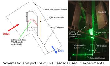
Microjets were implemented on the AFRL-designed L1A low-pressure turbine blade to examine their effect on the blade’s non-reattaching laminar separation. The effect of microjet control is examined through pressure and velocity field measurements. At the optimal jet blowing ratio (B), separation over the blade’s suction side is completely eliminated.
 |
 |
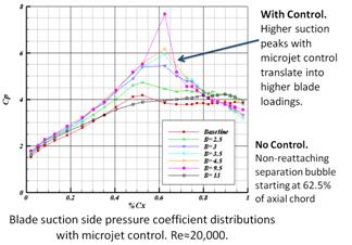
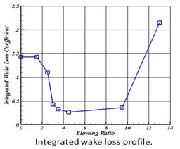
Coefficient of pressure (Cp) distributions show that when optimal microjet control is used the pressure plateau seen in the baseline case, due to separation, is eliminated and higher blade loading is realized. The elimination of the separated “long bubble” is crucial since it detrimentally alters the entire blade pressure distribution. Integrated wake loss plots show an 85% drop in wake loss when optimal control is used. With control, the blade’s performance approaches that of its high Reynolds number design.
 |
 |
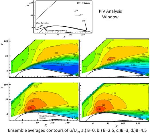
PIV Contours of velocity show a large region of reverse flow, shown as dark blue and negative values for the baseline case, i.e. no microjet blowing (B=0). With increased microjet blowing the separated region size is reduced until the flow is completely attached at B=4.5.
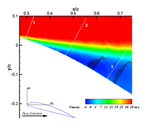
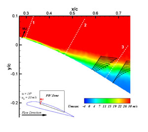
Microjet based actuators have shown substantial promise in the field of subsonic separation control. A set of steady microjet actuators has been implemented into a remote controlled (RC) airplane in order to test for microjet efficacy during actual flying conditions. Wind tunnel tests including CP measurements, surface flow visualizations, and particle image velocimetry (PIV) have been performed to study the flowfield over a section of the RC aircraft's wing. Microjets were installed and some of the tests were repeated showing an increase in the critical angle of attack (AOA - α) of at least 3 degrees. Below are two images from the PIV measurements; separated flow is seen in the image on the left and reattached flow through the use of microjet injection is seen on the right.
 |
 |
| a) | b) |
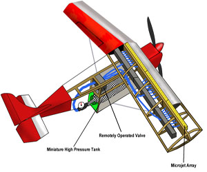
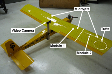
The RC airplane was modified with an air supply system and an array of microjet actuators that covers the entire wingspan (see the images below). A miniature video camera mounted on the airframe records the movement of tufts over one of the wings. By activating the microjet actuators over one half of each wing (module 1 or 2 separately), the flow both with and without control can be visualized simultaneously. Stall maneuvers were performed in which one part of the wing's tufts indicates separated flow (no control), and the other shows reattached flow due to the application of microjet control. Two LEDs on the wing tip indicate (to the video camera) when each of the microjet modules is activated. The results from the flight tests are consistent with the wind tunnel tests, thus illustrating that active flow control using microjets can be implemented and utilized on small scale UAVs.
 |
 |
| Design schematic showing the actuator system (Click on the picture for a larger view) |
The modified airplane (original model - 8' Senior Telemaster) |
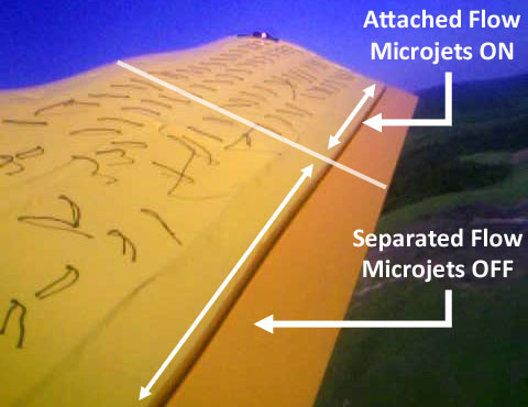 |
| Still image during stall maneuver Microjet control applied only on the wing tip section |
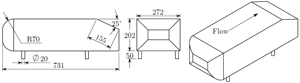
The aerodynamics of modern day vehicles have continued to be an important research topic due to their impact on fuel efficiency which directly relates to pressing environmental concerns. The flow field over a vehicle influences the drag and lift forces on the model, both of which are essential to an automobiles performance. In this research, an active flow control technique is applied on a generic fastback model to investigate its effect on the aerodynamic drag as well as the flow topology. The model used in this study is a 25ᵒ Ahmed model, shown below.
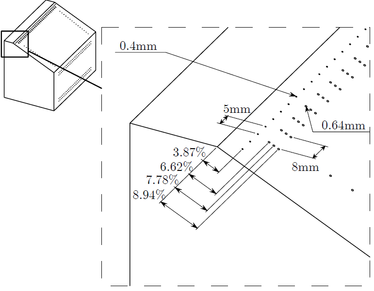
Throughout this study microjets are used as a control method to beneficially alter the characteristics of the flow field to improve overall aerodynamics. This active flow control study relies on injecting additional momentum into the flow by means of steady, discretely spaced jets aligned across the span of the model. Shown below are some configurations utilized to modify the separating flow on the rear end of the model. A single span wise array is actuated to gauge its effect on the flow field. Multiple streamwise injection locations were tested to examine the effect of control placement.
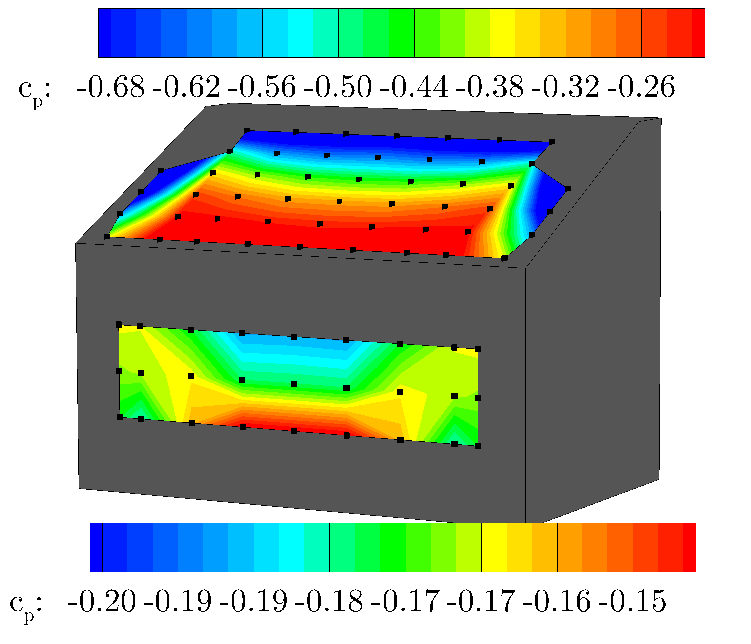
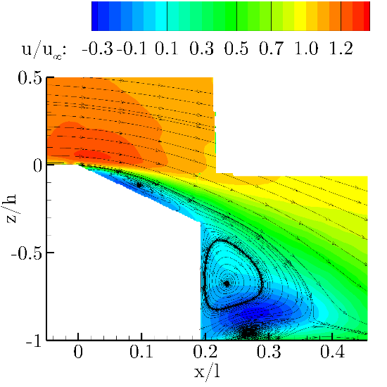
An investigation into the baseline case was conducted to determine the initial drag and lift values with no flow control applied. The reported values are CD= 0.391 and CL = 0.338. A contour of the pressure coefficient measurements can be seen in the following figure, where the strong adverse (increasing) pressure gradient appears in the center of the slant, causing the formation of a closed separation region, which is highlighted the corresponding PIV measurement. The PIV also shows the shape of the trailing wake vortices, containing a much larger upper region as compared to the lower and a reverse flow region which causes flow to impinge on the rear vertical base causing a locally high pressure region shown on the back surface of the baseline pressure measurement. For the baseline, the wake has a length of approximately lwake /L=0.16.
 |
 |
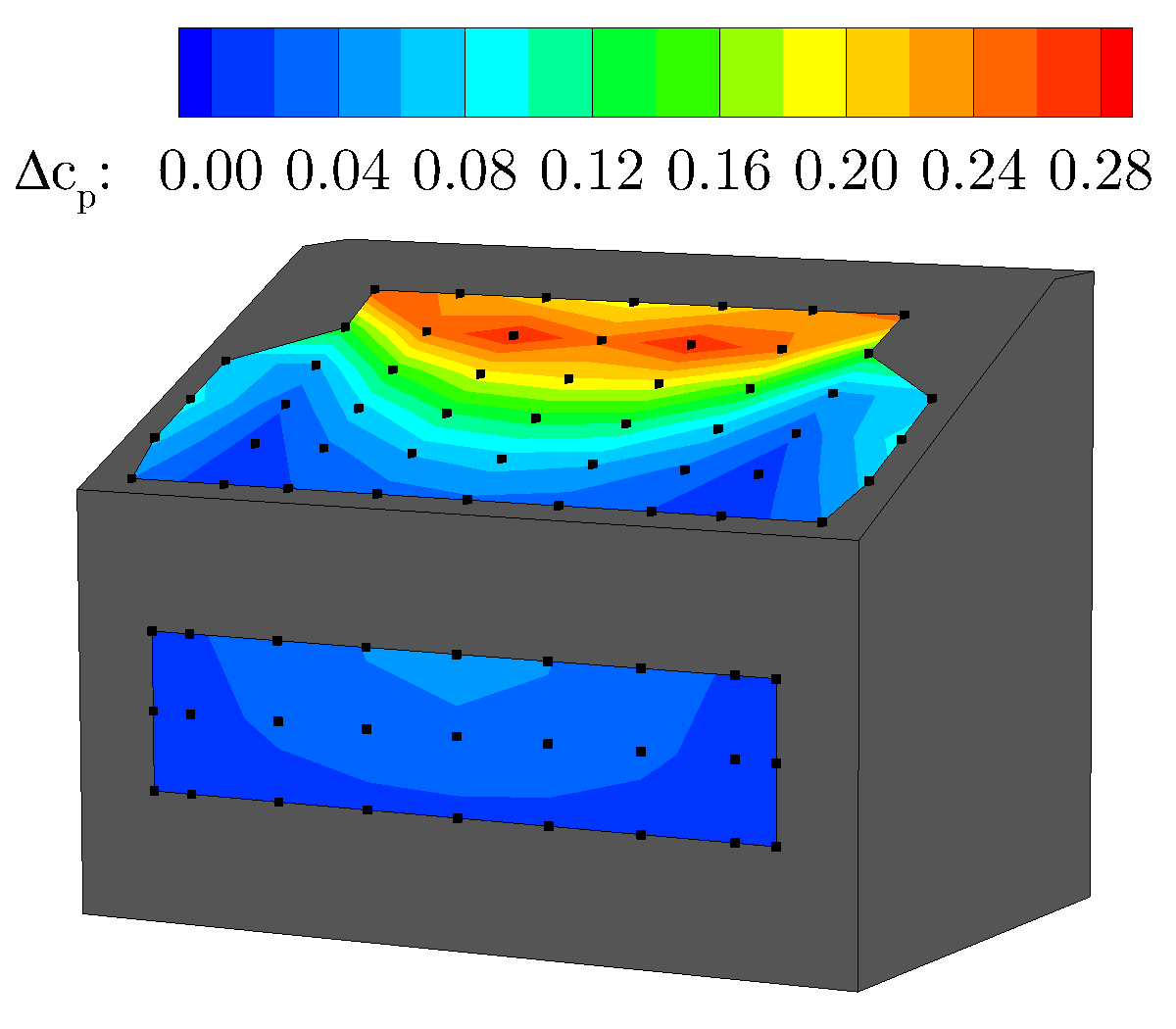
To highlight the effect of the control on the flow field and pressure distribution, a case is selected to compare to the baseline results (below). The case selected corresponds to a momentum coefficient of cμ=4.8% and a drag reduction of 10%.
 |
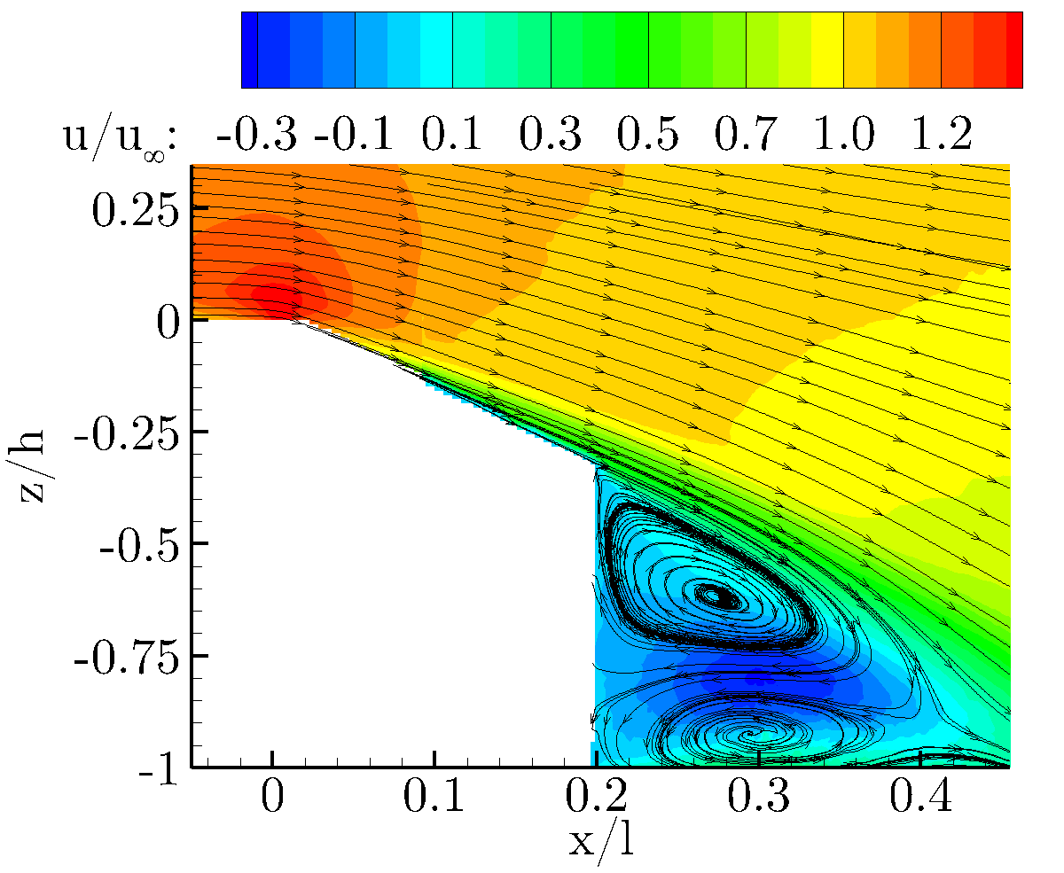 |
To highlight the effect on the pressure, the result for the presented case is expressed as the difference between the measured pressure and the baseline values. The pressure on a majority of the rear of the model is significantly increased, with large increases in pressure measured in the region just downstream of the control implementation. The large increase in pressure over the surface results in the large drag reduction. The corresponding PIV shows that this corresponds to an elimination of the separation bubble above the slant surface. The elimination of separation causes the fluid nearest the surface to increase in velocity, thus increasing the near wall momentum. The higher momentum fluid, then convects downstream causing the shear in the wake of the model to increase. The increase in shear force causes the trailing wake region to elongate. The elongation results in the time averaged position of the rotating vortices to stand further from the model. With the center of the recirculation being characterized by a low pressure core, moving the structures further from the model surface results in a higher pressure on the rear of the model, contributing to the drag reduction.
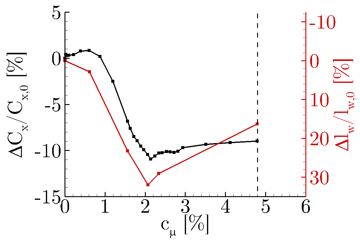
Varying the jet velocity (and momentum) reveals that the control can strongly effect the drag on the model, reducing the force by ~12%. The results plotted in the following figure show that there is a region in which the control can effectively alter the drag on the model and that the length of the trailing wake is strongly correlated to the measured drag force (highlighted by the similar trends as a function of the non-dimensional momentum coefficient (cμ).
[1] Sharma, O., “Impact of Reynolds Number on Low Pressure Turbine Performance,” NASA CP-1998-206958, 1998, 65-69.
[2] Weiss, J.M and Kelecy, F.J. "Numerical Simulation of Steady-State Flow Through a Multi-Stage Turbine Using Unstructured Meshes", Proceedings of the 3rd ASME/JSME Joint Fluids Engineering Conference, San Francisco, California, July 18-23, 1999.
[3] Clark, J.P., Praisner, T.J., Grover, E.A., Rice, M.J., “Predicting Transition in Turbomachinery-Part I: A Review and New Model Development,” Journal of Turbomachinery, Vol. 129 (2007), 1-13.DOI: 10.1115/1.2366513